M-Machine Information Library


How to use a Dividing Head and Rotary Index Table.

How to use a Dividing Head or Rotary Index Table

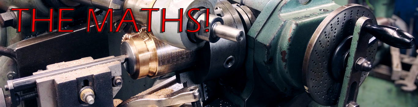
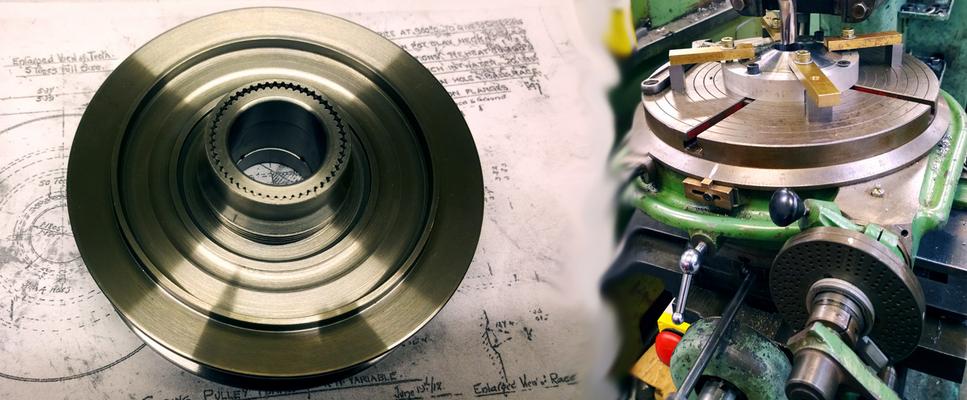
The divide head and rotary table are a device used to rotate the work piece around a third machine axis, this is usually referred to as the 'C' axis and is commonly used on milling machines or borers to provide the ability to easily create accurate single or multiple machining operations around a component.

A typical use would be to quickly machine a hexagon profile around a diameter, or to produce a series of cut-outs at a specific pitch from one another. The divide head is similar to that of mounting a lathe head on a milling machine table to produce a horizontal rotating axis, where as a rotary table is more commonly used to rotate the work piece vertically. Of course both devices may be mounted then moved in multiple orientations besides that mentioned above in order to produce the profile required.

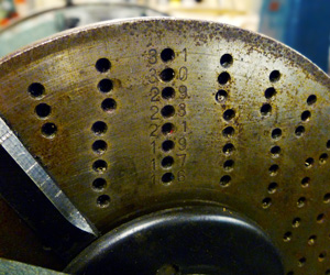
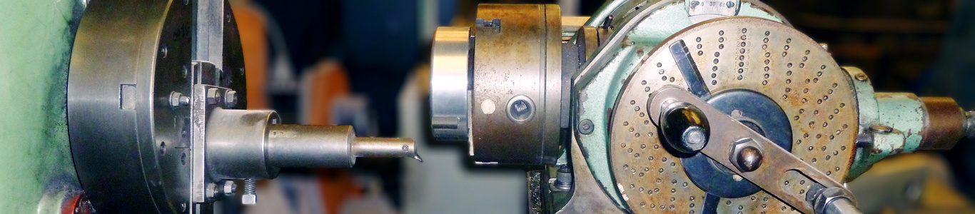
Movement of the device is a simple matter of rotating a handle in the desired direction until the degree of movement is obtained that you need to rotate the part. In simple use, the engineer would mark-off the work piece prior to mounting onto the 'C' axis, then having mounted a centre drill or pointer into the machine chuck - rotate the part until the markings align central to the spindle. Of course this method is only as accurate as ones marking-off and sight allows! Some cheaper devices are fitted with only a graduated dial for rotational movement, but for perfect precision the machinist must make use of the 'Hole Plate', which is an integral part of most 'older' or better quality dividing heads and rotary tables.

How to use the Hole Plate

Divide Head Hole Plate

The hole plate is a static circular plate mounted to the rear of the rotation handle which is pre-drilled with many equally spaced holes at a different series of pitches. The pitch decreases as one moves from the centre of the hole plate to the outer edge (made clearer on the photo to the right). The axis handle has both a sprung pin - which may be inserted into one of the holes as well as a set of ‘clock hands’ and pointers that aid repetitive movements. (we will come back to the pointers later in this paper)

The ratio of turns between the device handle and the chuck is set by the head/table manufacturer, commonly either 60:1 or 40:1. In the later case 40 turns of the device handle would give 1 complete turn of the chuck. This means that one rotation of the handle would produce 9 degrees of chuck movement. (360 degrees divided by 40 turns is equal to 9 degrees per turn of the handle)

So what the hole plate does is split every 9 degrees into a number of graduations - the holes on the hole plate. Marked on your device hole plate will be number that corresponds to the numbers of holes are drilled on a certain area of the hole plate. These numbers are to be used to quickly identify if the degree of chuck movement to produce the desired movement division can be achieved on one set of drilled holes. I know this sounds complicated but stick with it, hopefully the example below will clear the method up a bit! (one day I'll make an online calculator for this...)

Using the 'Clock Hands'

Divide Head Clock Hands

Most dividers are fitted with a set of 'clock hands', or pointers that are designed to aid quick location of the handle pin into a hole in the hole plate. These can be set to a specific number of holes about the hole plate to ensure that the engineer does not loose count of the holes during a chuck movement. The pointers are adjustable to rotate around the centre and can be moved independently as desired via releasing the locking screw. This can be found by gently rotating the centre cover until a screw head can be seen through a small inspection hole drilled into the cover.

Utilising the clock hands is achieved by aligning the first hand against the front of the handle pin, then counting the number of holes required to obtain the correct angular movement and setting the second hand about this hole location.

For example: If we know that we need 40 holes and we will be using a 21 division hole plate, we start off at any position (say, 12 o'clock) with the handle engaged on the hole plate. Set the first pointer against the front of the handle pin - then move the second pointer 2 holes anti-clockwise about the plate and secure the locking screw. Perform the machining operation at this position, then move the clock hands as a complete unit (both hands are now locked together via the locking screw) so that the second hand now touches the rear of the handle pin. Move the handle clockwise so that the handle pin is against the rear of the first pointer, in this case it works out to be one full rotation and nineteen holes - so move 21 holes(one rotation) + 19 holes = 40 holes in total). Continue this procedure until the machining operations are complete about the full 360 degree movement. It is important to remember to continue the rotational movements in the same direction about the entire machining operation. The dividing head will usually have a backlash adjuster in the mechanism which will tighten the internal gear mesh, but don't rely entirely on this as uneven wear in the mechanicals of the table may result in slight errors in movement.

How to use a Dividing Head or Rotary Index Table

How to calculate which hole plate to use and the number of holes to use per movement.

I'll try and make this as easy to understand as possible. It may look complicated to begin with, but as we work through the maths it should hopefully become quite straight forward.

Example and Method

In this example we will produce a set of 7 slots (or holes/details, I'll call them slots from now on), equally spaced all around the circumference of a diameter. This example assumes that you are using a 40:1 ratio divide head or rotary table - the maths are the same if you have a 60:1 or 80:1 ratio - just use the different figure when it comes to the total number of holes section.

The first thing to do is to work out the number of decimal degrees for the spacing of the slots, so that is 360 degrees (the whole circumference) divided by the 7 slots.

Divide Head, Maths

Next lets work out many times you need to turn the handle for each slot - this is only as a counting guide that we'll use later on. The number that we calculate will be used only for making counting between slots easier to remember. In our case of a 40:1 ratio: 360 degrees divided by 40 to 1 (360/40) = 9 degrees. So lets divide the result of the number of slots that you want (the previous calculation: 52.42857) over the 9 degrees. We know it is equal to 5.71428. This means that to get 7 slots over 360 degrees, you will turn the handle roughly five and three quarter turns per slot - or 5.7 turns.

Divide Head, Maths

Next we must work out the total number of holes on each hole series that are on the hole plate (the series being the hole ring group, the number of concentric holes on the hole plate). So, using a series of 21 holes - this would be: 21 holes X 40 turns = 840 holes per 360 degrees of rotation of the chuck. Remember that the dividing head that we're using is at 40:1 ratio, so you need to turn the handle 40 times to produce 360 degrees of movement at the chuck. If you are using a 60:1 or 80:1 then calculate using your ratio instead.

Listed to the right is all of the common hole plate series with the total number of holes per series already calculated for ease of following this tutorial. (using 40:1 ratio)

Divide Head, Maths

We must now find out which series of holes will exactly match the angular movement that we need. This is done by dividing the total number of holes on a given hole series by 360 degrees. This result must then be further divided by the result of our first calculation, which in this case is 51.42857. To break this down, we're aiming to use the 21 series hole plate, 21 holes x 40 turns = 840 holes. 360 degrees / 840 holes is 0.428571. Back to the first result of 360 degrees / 7 slots = 51.42857 / 0.428571 = 120.000 total number of holes per slot. 120.000 degrees / 21 holes is 5.712428, but now we've just calculated the exact number of turns and holes needed using a 21 series hole plate.

You now need to set the clock hands on the divider to 15 holes past the handle dowel, as 5 turns x 21 holes equals 105 holes, 15 holes remain to give a total of 120 holes per movement - so 5 turns, 15 holes on a 21 series hole plate.

Divide Head, Maths

With this example we already knew that a 21 hole plate would provide the best whole number result - but this will not always be the case. In reality you will have to use a bit of trial and error going through all your series of available hole plates until you can obtain the nearest result to a whole number that you can. This process may seem a bit 'heath robinson' but the engineer will soon become more accustomed to the procedure and will soon be able to make an educated guess as to the probable best hole plate to use for a given number of required slots. It is important to note that you may not be able to achive a 'perfect' whole number, as in the example above the actual result was 120.0001166667 - but given that we're limited by a mechanical indexed device, our result was near enough perfect!

The aim is to find the nearest result to a whole number that is possible given the hole series available on your hole plates.

Divide Head, Maths
How to use a Dividing Head or Rotary Index Table
 

Want to ask a question?

If you want to place and order then the quickest way is to either telephone or email, currently we don't take orders on-line as we're old fasioned and like to write things down (this way we know if we have physical material stock on our shelves for an enquiry.) We're always available to help with a material selection or advise on an engineered part, please feel free to give us a call as one of our engineers will be happy to help.

Get in touch»


WHO WE ARE

We're a small business trading under the name of M-Machine, our registered company name is Craftgrange Limited. We operate from the UK under the registration number of 01476185 and were established in 1980 to supply pressed steel panels, engineered parts and materials to business and general public.

Learn more about who we are »

HOW TO CONTACT US

M-Machine
Unit 3 to 7 Forge Way, Cleveland Trading Estate
Darlington, County Durham, DL1 2PJ. UK
P: (01325)381302 (Metals and Engineering)
P: (01325)381300 (Mini Pressings and Accounts)
E: Get in touch via e-mail

FIND US

What3Words Location: recent.guards.cover